Practical configuration for reducing energy consumption in concrete batching plants
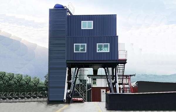
1. Wind trough replaces screw conveyor for conveying powder materials
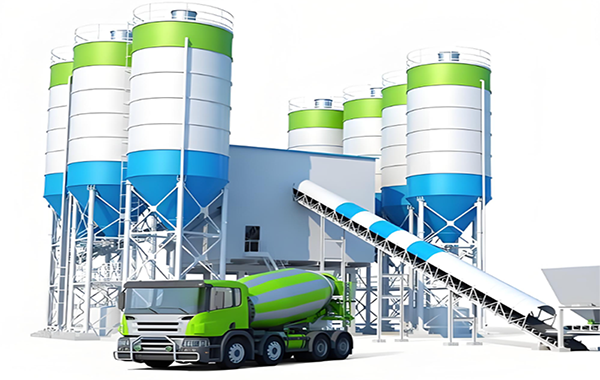
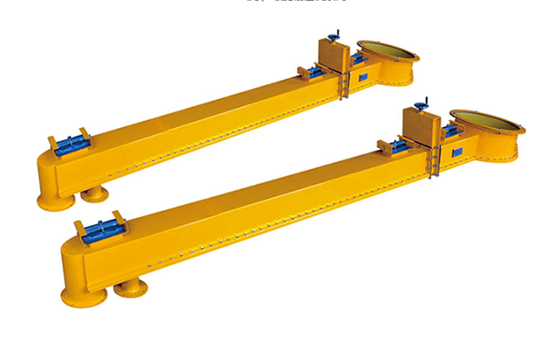
With the continuous increase in the capacity of concrete mixing plants, traditional screw conveyors have gradually become unable to meet the conveying requirements, and wind-driven inclined chutes with large conveying capacity have become a better choice.
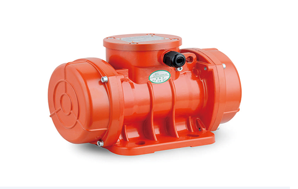
The wind-driven inclined chute belongs to fluidized bed conveying equipment, which can transport powdered materials with a particle size of 3-6mm or less. It is mainly used for conveying cement, fly ash, and other non viscous powdered materials. The wind trough is composed of two trough shaped shells, with a wear-resistant, high-temperature resistant, and breathable layer sandwiched between the upper and lower shells. The entire shell is arranged at a certain slope, and the material is added by the feeding equipment. The upper shell is powered by medium and high-pressure fans, and the gas permeable layer makes the material fluidized. The inflated material flows forward along the slope to achieve the conveying purpose. A small slope of the air duct is beneficial for process design, while a large slope is beneficial for material flow. Compared with mechanical conveying devices such as screw conveyors, it has the following characteristics:
(1) Directly transporting bulk materials, with high operational efficiency and large conveying capacity;
(2) The equipment has a simple structure, small footprint, no rotating parts in the main body, light weight, long service life, and significantly reduced maintenance costs;
(3) With fewer operators, fully automated remote control management can be achieved at a lower cost;
(4) It can ensure that the transported materials are not affected by moisture or dirt, and reduce dust flying, improving environmental hygiene. Among them, in terms of energy consumption, the advantage of Z is that it eliminates the need for power equipment and does not require rotating parts
2. Self drop type replaces booster pump for pressurized water supply
In concrete production, it is necessary to provide liquids such as water and additives. According to the feeding sequence in the concrete production process, the liquid should be added before the aggregate, and the wave body should have a certain pressure to ensure that the concrete is mixed more evenly within the set time.
In the past, liquid pressure was achieved through a booster pump. For a 2m3 engine, a 7.5kW booster pump was used, while for a 3-4m3 engine, an 11kW booster pump was used. Considering that the potential energy of the liquid will generate a certain pressure, the form of liquid injection will be changed to self falling. To ensure that the liquid sprayed from the feeding material spray pipe has a considerable pressure, the bottom outlet of the water scale is also raised to a certain height to increase the drop and ensure pressure. By timing the self falling liquid feeding, the liquid feeding time is almost the same as that of the booster pump. This method has been widely used in 2-3m3 main mixing plants, and the entire mixing plant has saved 7.5-11kW of installed capacity in this improvement.
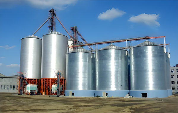
3. Layout of gas supply system for 1 machine and 2 packages
The air pressure system of a concrete mixing plant (station) mainly includes an air compressor and a gas storage tank. The air compressor provides the air source, while the air storage bag ensures the stability of the air pressure. In the past, the configuration of mixing plants (stations) was either 2 air compressors or 2 air compressors plus 1 air storage bag. Practice has proven that without a gas storage bag or having only one gas storage bag, it is impossible to ensure the stability of the gas source for both the main body and the backstage of the mixing plant (station) at the same time, and having two gas storage bags for two air compressors is somewhat redundant. Through practical exploration, a reasonable configuration of 1 air compressor and 2 air storage bags has been formed.
4. Improve the flushing water circuit of the belt conveyor
The water required for concrete production is transported to the measuring scale through the conveying pipeline. Due to the fact that sand and other aggregates are usually directly stored in the open air and exposed to wind and rain, their moisture content will increase to varying degrees. Sand with high moisture content will adhere to the conveyor belt during transportation, increasing the wear rate of the belt and reducing its service life. Therefore, it is necessary to flush the belt irregularly. In the past, a 3kW water pump was used to directly supply water to the head of the inclined belt conveyor for flushing. Through improvement, a branch was separated from the pipeline supplying water to the scale, and the flushing of the inclined belt conveyor was controlled by a ball valve. The improved pipeline is not only simpler to manufacture, but also reduces the use of one 3kW water pump.
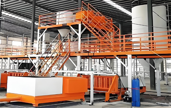
5. Configure a high-level water tank to reduce the power of the water supply pump
The function of the high-level water tank is equivalent to a transfer water tank, and it is relatively close to the water scale, which can reduce the time consumed by water during transportation and lower the power requirements of the water pump. For a 3m3 main mixing plant, the previous pump power was 7 5kW, with the installation of a high-level water tank, the power of the water pump can be reduced to 5.5kW. There are many other configurations to reduce energy consumption, such as using 24V voltage for the solenoid valve, using the urban water supply network to supply water to the mixing plant, pulse back blowing vibration dust collector, etc. In practice, not only can it bring certain economic benefits to users, but more importantly, it reduces the energy consumption of the product.